In this comprehensive guide, we will dissect the components of a battery energy storage system diagram, explore the differences between AC and DC coupling, and help you identify the right configuration for your commercial or residential needs. These blueprints hold the key to optimizing grid resilience - but what exactly makes these diagrams so. . aviors of battery energy storage systems. It's more than just a drawing; it is a detailed plan that illustrates how every component connects and interacts to generate, store, and deliver power.
[PDF Version]
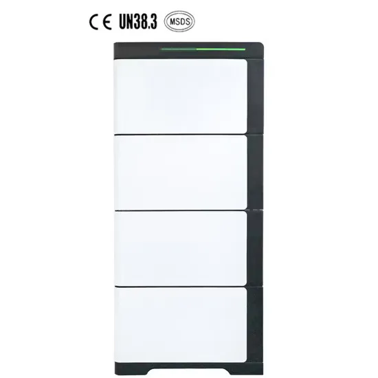
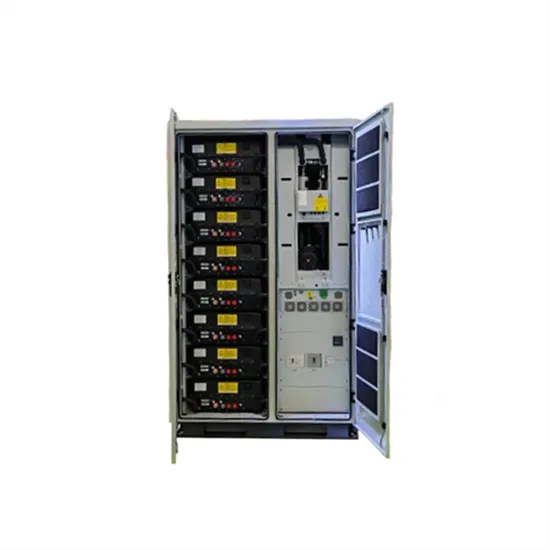
In this comprehensive guide, we will dissect the components of a battery energy storage system diagram, explore the differences between AC and DC coupling, and help you identify the right configuration for your commercial or residential needs. It's more than just a drawing; it is a detailed plan that illustrates how every component connects and interacts to generate, store, and deliver power. For homeowners, installers, and DIY. . “Parallel Operation of Energy Storage” – a source operated in parallel with the grid when it is connected to the distribution grid and can supply energy to the Interconnection Customer simultaneously with the Company's supply of energy3. “Operating Mode” – a combination of the functionality in the. . A BESS is a carefully designed, integrated setup that goes far beyond storing electricity. For this guide, we focus on lithium-based systems, which dominate over 90% of the market. The battery is a crucial. .
[PDF Version]
The report highlights how LiquidShield™ immersion cooling delivers consistent thermal control, reduces degradation, and prevents fire propagation, setting a new benchmark for safe, high-performance battery energy storage systems. . EticaAG is featured in Energy Storage News' Annual Report 2026, showcasing its integrated fire and gas safety platform. Unlike traditional radiators used in internal combustion engines, new energy vehicle radiators are designed specifically for electric powertrains, batteries, and associated electronics. Consumers, utilities, and policymakers also consider storage “duration” or how long an energy storage. . Heat storage is the process of capturing thermal energy for use at a later time, playing a key role in enhancing energy eficiency and enabling renewable energy integration. A conceptual architecture for the SH Thermal Control System (TCS) is presented. A TCS dual loop design is. . Depends on both on Phase 2 and deployment of variable generation resources While the Phases are roughly sequential there is considerable overlap and uncertainty. Key Learning 2: Recent storage cost declines are projected to continue, with. .
[PDF Version]
At the heart of this understanding lies the battery energy storage system diagram—a visual roadmap that explains how energy flows, how safety is managed, and how power is converted. Flywheel Energy Storage: Your Childhood Top Went Pro Picture your old spinning top—now make it weigh 10 tons and spin at 40,000 RPM. That's flywheel energy. . Compressed-air-energy storage (CAES) is a way to for later use using. At a scale, energy generated during periods of low demand can be released during periods. The first utility-scale CAES project was in the Huntorf power plant in, and is still operational as of 2024. Various strategies including hybridization, doping, pore structure control, composite formation and surface functionalization for improving the capacitance an ic energy, and release out upon demand. They work by spinning up a heavy disk or rotor to high. .
[PDF Version]
The figure below shows the schematic diagram of a chilled water system with heat recovery chiller. . ceeding energy code minimum requirements. A comprehensive approach to system design can minimize the power draw of the entire system are inherently easier to control for highest eficiency, lower first costs and lower energy costs. Right-sizing equipment means smaller electrical conne tions—a great. . Thermal Energy Storage (TES) for space cooling, also known as cool storage, chill storage, or cool thermal storage, is a cost saving technique for allowing energy-intensive, electrically driven cooling equipment to be predominantly operated during off-peak hours when electricity rates are lower. The impurities in the cooling water circuit are accumulated, and thus the scales and deposits are built up in the condenser tubes, creating fouling problems on the condenser heat. . entropically as shown by the curve 1-2 on p-v and T-s diagrams. Any Questions? A chiller is a heat transfer device.
[PDF Version]
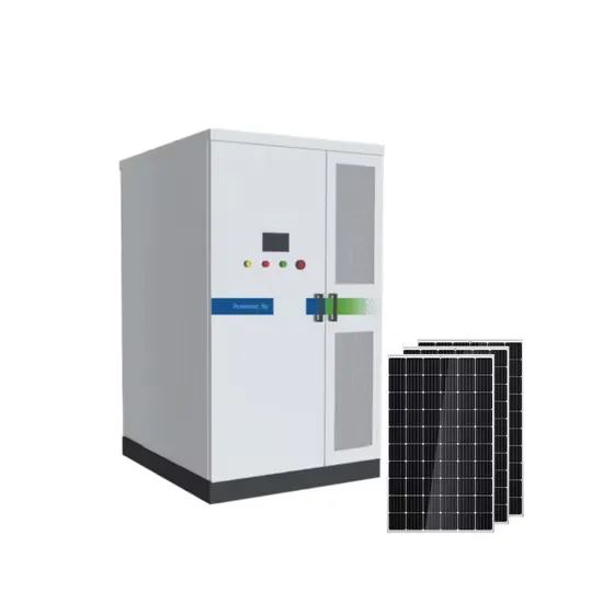
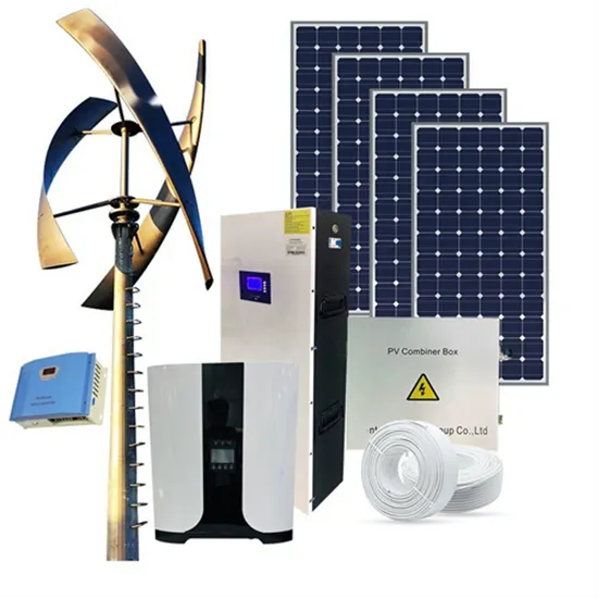
A detailed solar energy storage system diagram breakdown, explaining components, configurations, and design principles for achieving energy independence. . ce data,making reporting and forecasting easy. Size the productio RCD to the production circu t size or highe. Excess electricity and energy stored in the battery during the day will help feed the house during peak consumption and energy cost. . A typical structure of the Battery Energy Storage System (BESS) is illustrated in Figure 2, which mainly includes battery cells, Battery Management System (BMS), Power Conversion. For homeowners, installers, and DIY. .
[PDF Version]